2012 Honda CBR250R/RA Valve Adjustment Procedure - Page 3
Prev | Next19. Remove the two valve cover bolts (see image below).
20. Remove the valve cover and pass it through the frame tubes above the lowered radiator. You need to lift the valve cover to clear the camshaft sprockets. There is not much extra room, and you may need to fiddle with the valve cover to remove it.
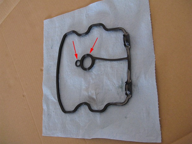
21. Remove the valve cover rubber gasket / seal from the valve cover (see image of seal below). The small circular portion goes on the locating dowel in the valve cover. The larger circular portion seals the hole for the spark plug.
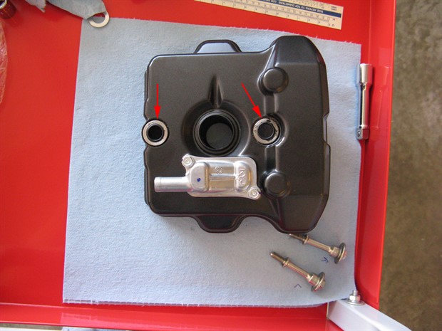
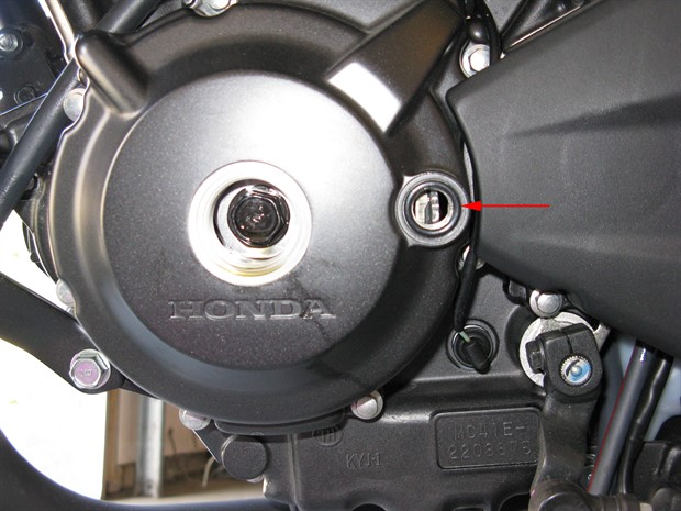
22. Clean and inspect the valve cover bolt seals and replace them if damaged or deteriorated (see image below). You don't want any sand or dirt trapped under the seals when you re-install the valve cover later.
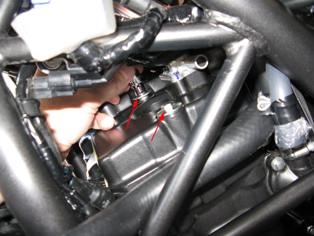
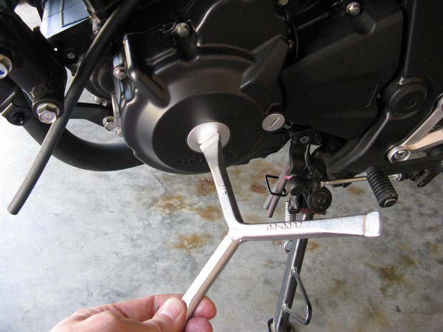
23. Remove the crankshaft hole cap and the timing hole cap. I used a slightly modified Motion Pro timing plug wrench to undo the caps (see image below). I had to grind the two smaller blades thinner to fit the grooves in the caps.
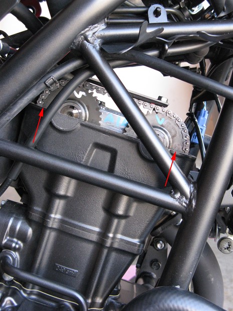
24. Rotate the crankshaft until the “T” mark on the flywheel aligns with the notch in the timing cap hole of the crankcase cover and the camshaft sprockets are in the correct position: “EX” (exhaust) to the front, “IN” (intake) to the rear and the associated marks align with the cylinder head top edge (see images below). If the marks on the camshaft sprockets are not in the correct position when the "T" mark is aligned, rotate the crankshaft another 360 degrees. The service manual states, in multiple places, to rotate the crankshaft counter-clockwise, but in one place I found the manual states to rotate the crankshaft clockwise. I'm assuming that the clockwise reference is an error.
25. Measure and record the valve clearances (2 intake and 2 exhaust). Measure and adjust the valve clearances when the engine is cold (below 35C / 95F). It can be difficult to get a feeler gauge positioned correctly and inserted into the space between the shim and the rocker arm because the gauges need to be bent. Of course, if you have angled feeler guages, the task will be easier. If you do not have angled feeler gauges, it may be easier to combine thinner gauges than to use a single thicker one. It is important to note that the shims sit in recesses, and if the shim top is below the top of the recess, you may not be able to get an accurate measurement unless you use a tapered or very narrow feeler guage. There should be only a light drag (resistance) on the feeler gauge when you move it in and out of the space between the shim and the rocker arm. If the valve clearances are in spec, skip ahead.
Intake valve clearance: 0.16 +/- 0.03 mm (0.006 +/- 0.001 in) - verify in the service manual, owner's manual or with a Honda dealer
Exhaust valve clearance: 0.27 +/- 0.03 mm (0.011 +/- 0.001 in) - verify in the service manual, owner's manual or with a Honda dealer
The valve clearances are the same for the CRF300L and Rally (2021-2022 Honda CRF300L/LA/LR/LRA Factory Service Manual).
Prev | Next