2022 Honda CRF250F Valve Adjustment Procedure - Page 2
Prev | NextThis page includes the steps for checking the valve clearances. The following page covers the adjustment procedure. Measure and adjust the valve clearances when the engine is cold (below 35C / 95F).
1. It is a good idea to clean the motorcycle first, especially the top of the engine and the area above it like the underside of the fuel tank. You don’t want dirt falling into the engine. It’s also nicer to work on a clean motorcycle.
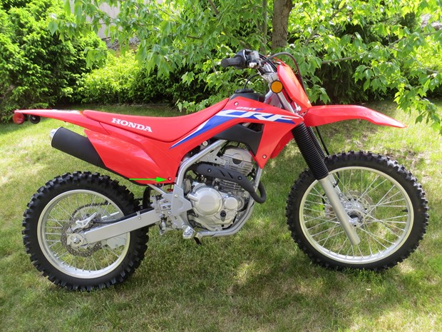
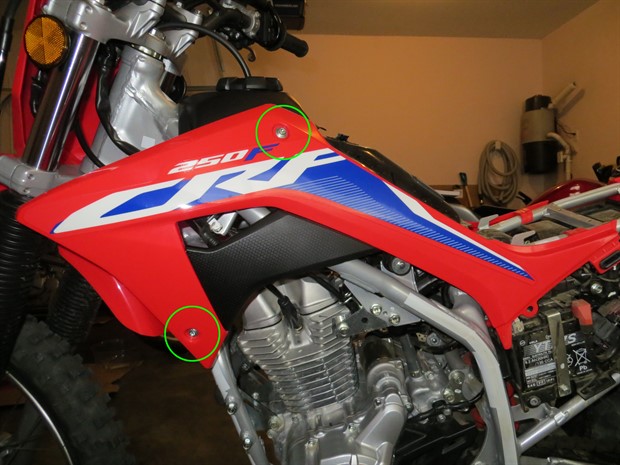
2. Remove the side panels. There is one bolt, an alignment tab and a couple of rubber grommets securing each side panel.
3. Remove the seat. Remove the two bolts under the rear fender. Pull the seat towards the rear of the bike to remove.
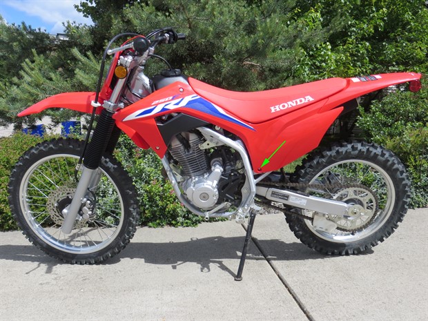
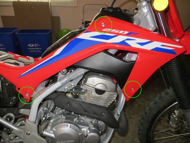
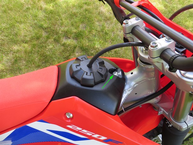
4. Remove the fuel tank shrouds. There are 2 bolts on the left side and 3 bolts on the right side.
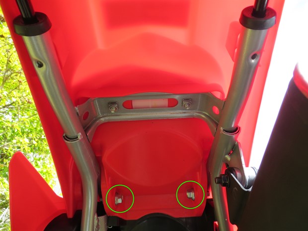
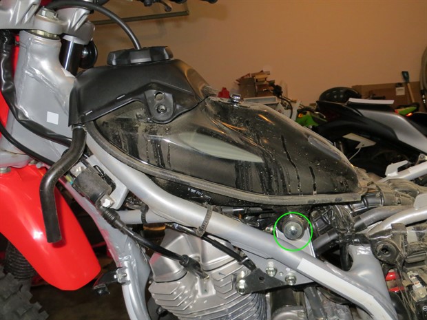
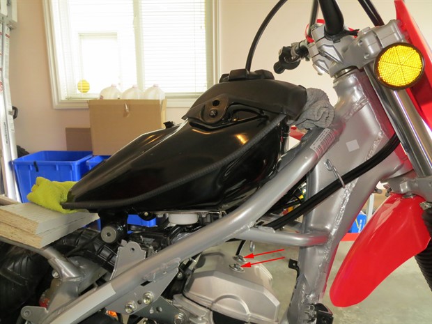
5. Lift the fuel tank. Remove the front fuel tank mounting bolt. You may want to loosen the two rear tank mounting bolts. Lift the tank a bit and support it. With the fuel tank lifted, the access for checking and adjusting the valve clearances is quite good. You can remove the rear tank mounting bolts (support the tank) to increase the access to the valves even more. If you want even better access, you can completely remove the fuel tank, but it’s not necessary.
To remove the fuel tank, disconnect the fuel pump 5P connector, relieve fuel pressure (run bike until it stalls, then turn off), disconnect the negative wire on the battery, put a rag under the fuel line connector to catch gas, disconnect the fuel line at the fuel pump (push retainer tab forward), wrap the fuel pipe end and the fuel line end with clean plastic bags, and remove the 2 rear tank mounting bolts. Lift the fuel tank off of the bike and place it on a secure surface with no weight on the fuel pipe or the connectors.
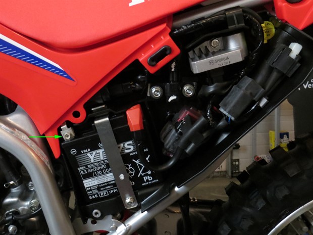
6. If you haven't already done so, consider disconnecting the negative wire on the battery.
7. Disconnect the spark plug cap from the spark plug and move out of the way. Do not pull on the spark plug wire.
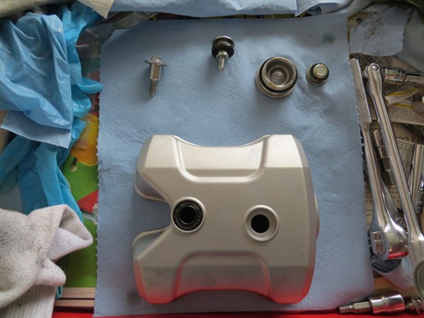
8. Remove the cylinder head cover (valve cover) by removing the two valve cover bolts. There are rubber seals for the valve cover bolts, and they are supposed to be marked with the word "UP" on the top surface. Make note of the way the seals are situated in case the "UP" markings are not legible. If possible, leave the rubber gasket on the cylinder head. In particular, if you can leave the semicircle shaped portion attached to the cylinder head, it may save you a step later on. If the valve cover is stuck, you can tap it lightly on the side with a rubber mallet to loosen it.
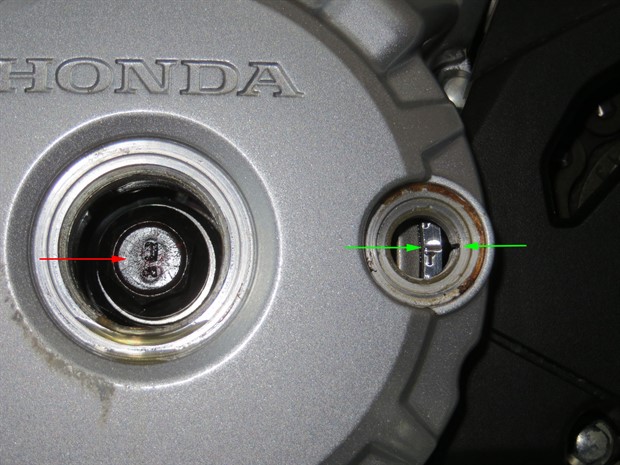
9. Remove the timing hole cap.
10. Remove the crankshaft hole cap.
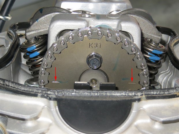
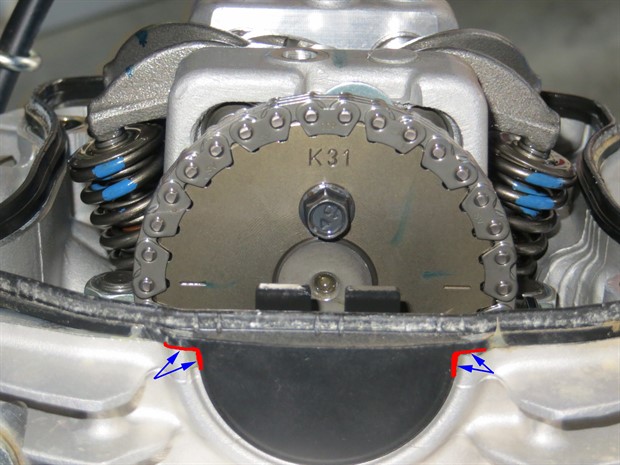
11. Rotate the crankshaft counterclockwise until the “T” mark on the flywheel aligns with the notch on the crankcase cover (on right side of hole). It’s easier if you use a flex bar or T-handle rather than a ratchet. Removing the spark plug can also make things easier. If you go past the “T” mark, keep rotating the crankshaft counterclockwise until the “T” mark lines up again. If the index lines on the camshaft sprocket don’t align with the top edge of the cylinder head, rotate the crankshaft counterclockwise a full revolution and align the “T” mark again. The piston should be at TDC on the compression stroke. The camshaft lobes should be generally pointing downwards, and you should be able to wiggle the rocker arms a bit.
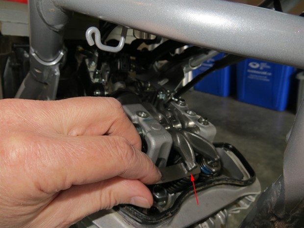
12. Check the valve clearances with a feeler gauge and write them down (example, exhaust, right side). Insert the feeler gauge between the rocker arm and the shim. There should be light drag on the feeler gauge. The shims sit in recesses, and if the shim top is below the top of the recess, you may not be able to get an accurate measurement unless you use a tapered or very narrow feeler guage. If the valve clearances are out of spec, goto the next page, for instructions on adjusting the valve clearances, otherwise put things back together as follows.
13. To install the valve cover gasket, apply high temperature resistant black silicone sealant (Three bond 5211, SS KE45, or equivalent) to the semicircle cut out in the cylinder head (top, outer side) corresponding to the semicircle portion of the rubber gasket if the gasket was removed previously. The service manual states to use a new rubber gasket, but as long as the old one is not damaged or deteriorated and is clean, you can likely reuse it (I have reused the rubber valve cover gasket on this bike and others without issue).
14. Ensure that the mating surfaces of the valve cover and cylinder head are clean. Ensure that the recesses for the valve cover bolt seals are clean. Install the cylinder head (valve) cover ensuring that the rubber gasket is in place. The service manual states to install a new gasket into the cylinder head cover and then install the the cylinder head cover onto the cylinder head.
15. Ensure that the rubber seals for the valve cover bolts are clean and in good condition. Insert the rubber seals into the valve cover with the “UP” marks facing up. The "UP" marks were not very legible on the seals of my bike.
16. Insert and tighten the cylinder head cover (valve cover) bolts to 10 N.m (7 lbf.ft).
17. Install the timing hole cap. Apply oil to the threads and O-ring and tighten to 10 N.m (7 lbf.ft). The service manual states to use a new O-ring, but if the old one is in good condition, you can likely reuse it
18. Install the crankshaft hole cap. Apply oil to the threads and O-ring and tighten to 15 N.m (11 lbf.ft). The service manual states to use a new O-ring, but if the old one is in good condition, you can likely reuse it.
19. If the fuel tank was removed, reconnect the fuel line. When reconnecting the fuel line, the connector retainer should click when completely pushed onto the fuel pump pipe end. You can put a bit of oil on the pipe end to make it easier to push the connector on. Reconnect the fuel pump 5P connector. Install the rear mounting bolts. Reconnect the negative battery wire. If the fuel tank was only raised, just lower the fuel tank into position.
20. If the rear fuel tank mounting bolts were removed, reinstall them if you haven’t already, but don’t tighten them yet.
21. Insert and tighten the front fuel tank mounting bolt to 27 N.m (20 lbf.ft).
22. Tighten up the rear fuel tank mounting bolts if they were loosened previously.
23. If the fuel line was disconnected, ensure that there are no fuel leaks.
24. Push the spark plug cap back onto the spark plug.
25. Reconnect the negative battery wire if was previously disconnected and has not yet been reconnected.
26. Install the tank shrouds.
27. Install the seat.
28. Install the side covers.
All done!
Prev | Next