2022 Honda CRF250F Valve Adjustment Procedure - Page 3
Prev |This page covers the steps for adjusting the valve clearances (after checking the valve clearances on the previous page) based on the author's experience adjusting the valve clearances on other motorcycles and information contained in the CRF250F service manual as the valves clearances on the author's CRF250F have not yet required adjustment.
1. Block any holes in the cylinder head with shop rags to prevent bolts, shims, etc. from falling into the engine.
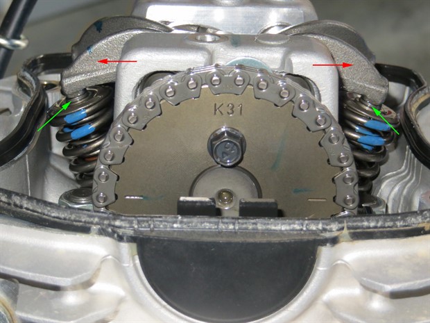
2. Remove the rocker arm shaft stopper bolt(s) corresponding to the valve(s) that require adjustment. Be careful not to drop the bolt(s) into the engine.
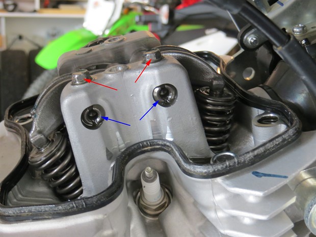
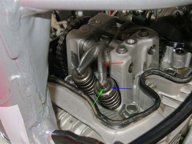
3. Remove the rocker arm(s) corresponding to the valve(s) that require adjustment. Thread a 6 mm bolt (valve cover bolt) into the hole in the rocker arm shaft(s) on left side of the engine and pull out the shaft(s) from the cylinder head while holding the rocker arm(s). Place parts on a clean surface and note where each part came from.
4. Remove the shims for the valves whose clearances need adjustment. Shims can be removed from the valve spring retainer with a magnet. Be careful not to drop the shims into the engine. Note the location of each removed shim.
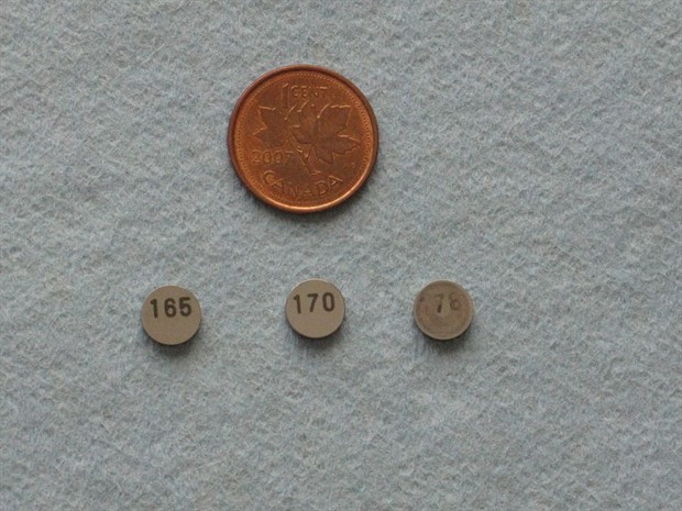
5. Determine the correct size of replacement shims:
new shim thickness = (measured valve clearance minus specified valve clearance) plus old shim thickness.
Confirm the thickness of the shims by measuring them with a micrometer.
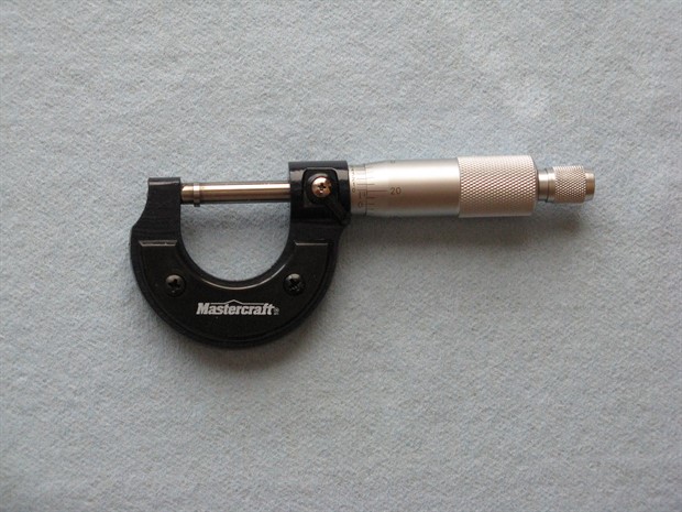
6. Get the required shims if you don’t have them. Confirm the thickness of the new shims by measuring them with a micrometer.
7. Install the new shims in the correct location. Flat-bladed tweezers may help. Be careful not to drop the shims into the engine.
8. Apply molybdenum oil mixture (1 to 1 ratio of molybdenum grease and motor oil) to the rocker arm inner surfaces, thrust surface and rocker arm shaft outer surface. Install the rocker arm(s), rocker arm shaft(s) and rocker arm shaft stopper bolt(s). Tighten the rocker arm shaft stopper bolt(s) to 5.2 N.m (3.8 lbf.ft).
9. Rotate the crankshaft counterclockwise several times and then recheck the valve clearances as before.
10. If all is good, put things back together as described in the Valve Clearance Inspection section on the previous page. Remember to first remove any shop rags, etc. from the cylinder head area.
The service manual states to check the idle speed after this procedure.
End of guide.
Prev |