2010 Suzuki DR650SE Valve Adjustment - Page 3
PreviousThis page covers the steps for checking and adjusting the valve clearances. Measure and adjust the valve clearances when the engine is cold (room temperature, below 35C / 95F).
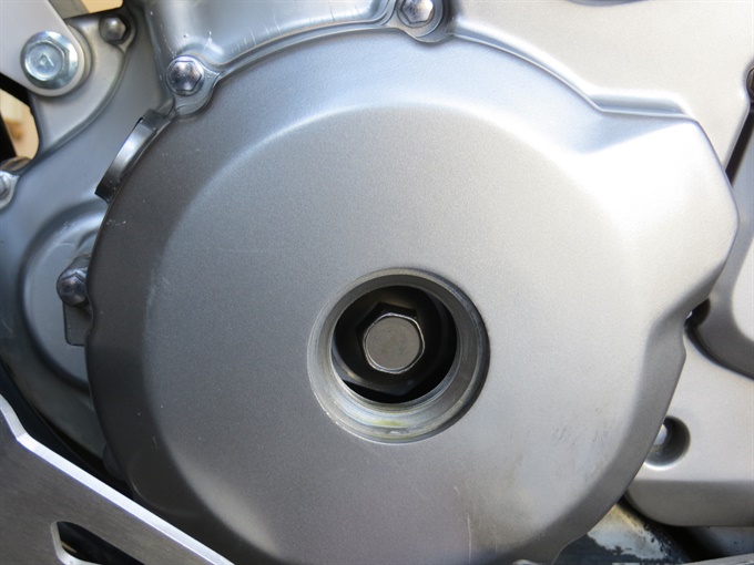
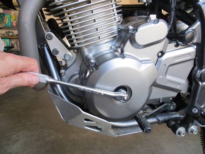
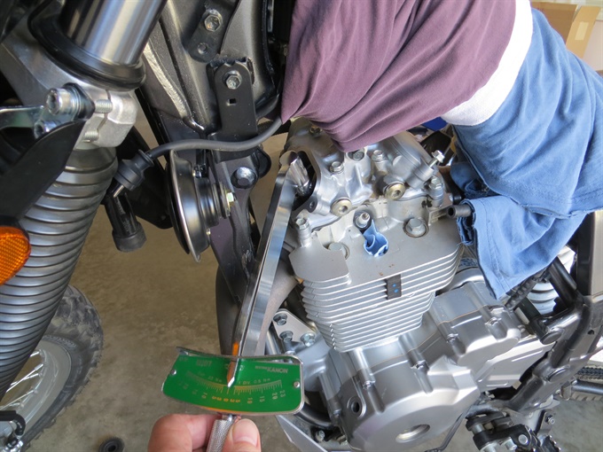
12. Set the engine piston at top dead centre (TDC) on the compression stroke for correct measurement of the valve clearances. Using a socket and flex-bar or T-handle on the crankshaft bolt accessible through the generator cover hole, rotate the crankshaft counter clockwise until the timing (T-mark) mark on the flywheel is in the centre of the timing hole in the crankcase cover (TDC plug removed). It’s usually easier if you use a flex-bar or T-handle rather than a ratchet. Removing the spark plug before hand makes this easier. If you go past the T-mark, keep rotating the crankshaft counter clockwise until the T-mark lines up again. If you cannot wiggle both intake and exhaust rocker arms (valve clearance adjusters) with your fingers, then the piston is likely not at the top of the compression stroke, so you'll need to rotate the crankshaft counter clockwise a full revolution and align the T-mark again.
13. Check the valve clearances with feeler gauges and write the measurements down (example, exhaust, right side). Insert the feeler gauge in the space between the valve stem and the adjusting screw on the rocker arm. There should be light drag on the feeler gauge. I've found that it's more difficult to measure the exhaust valve clearances than the intakes because the access is not as good. You may need to use angled feeler gauges. If you don't have angled feeler gauges, you can carefully bend standard flat ones. Don't insert the bent portion of the feeler gauge into the space to be measured, though. If the valve clearances are out of spec, you'll need to adjust them, otherwise you can skip ahead and put things back together.
Valve Clearances (per Suzuki DR650SE service manual) Engine cold: room temperature, below 35C (95F)Intake: 0.08 - 0.13 mm (0.003 - 0.005 in.)
Exhaust: 0.17 - 0.22 mm (0.007 - 0.009 in.)
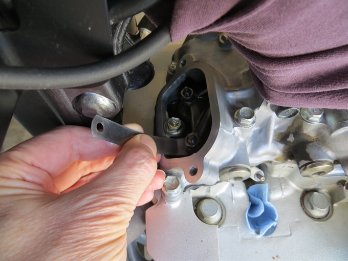
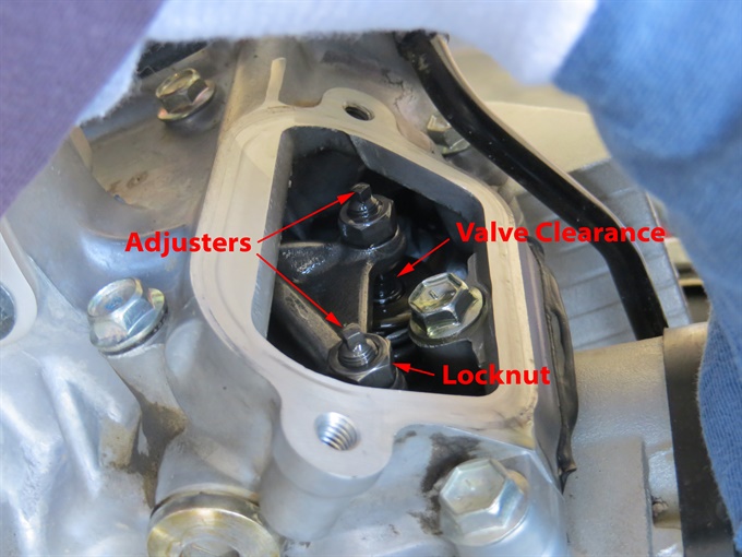
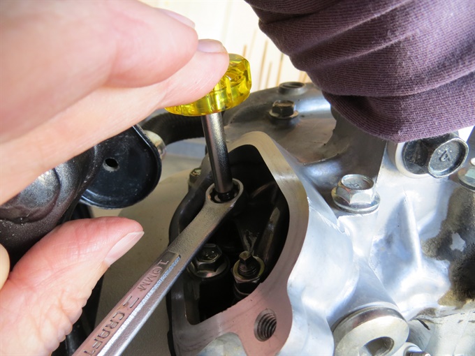
14. Adjust the valve clearances if they are out of specification (or at their limits). Do one valve at a time. Loosen the locknut with a clean 10 mm box-end wrench (or ratchet and clean 10 mm socket), and then turn the adjuster screw until the valve clearance is in spec. You can turn the adjuster with the correct size feeler gauge in place (in the gap) until you feel a bit of resistance, and then very slightly loosen the adjuster and remove the feeler gauge. While holding the adjuster screw (3 mm square end) with the special tool (or a 3 mm wrench), tighten the locknut with the box-end wrench. Check the valve clearance and readjust if necessary.
I try to set the valve clearances close to, or slightly above the mid point of the range. This often requires me to make multiple attempts. If all you care about is getting the clearances in range, then you can probably complete the task quicker. It's better if the valve clearances are on the looser side than on the tighter side.
Finally, tighten the locknut securely and then recheck the valve clearance. The DR650SE service manual does not specify a torque value for the locknuts. For reference, the 2020 Kawasaki KLX140 factory service manual specifies 8.8 N.m (78 in-lb) for its valve adjusting screw locknuts.
15. Recheck all of the valve clearances, and re-adjust them if necessary.
16. Install the valve inspection caps. Make sure that the mating surfaces are clean and that the rubber gasket is in good condition. Apply a bit of motor oil to the rubber gasket. The service manual does not specify a torque value for the cap bolts, but it does specify a torque value for the cylinder cover bolts: 10 N.m (7.0 lb-ft). Also for reference, the 2020 Kawasaki KLX140 factory service manual specifies 8.8 N.m (78 in-lb) for its valve adjusting cap bolts.
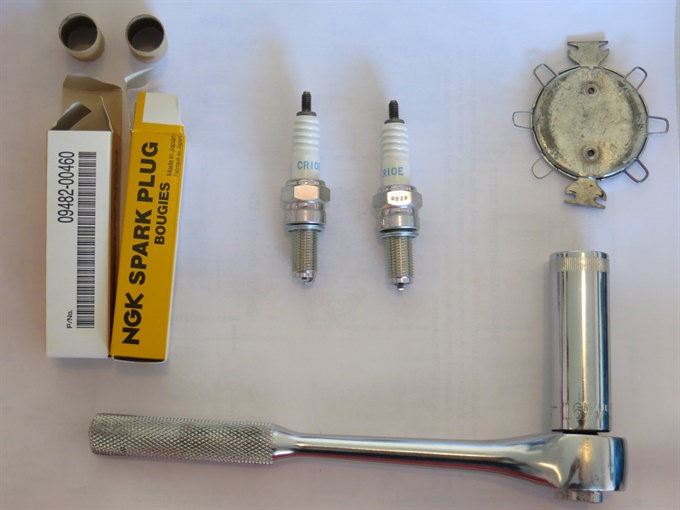
17. Install the removed spark plug(s) or new ones and tighten to 11 N.m (8.0 lbf-ft). Push the spark plug cap(s) back on. With about 25,400 km on the author's bike, new spark plugs were installed.

18. Install the valve timing inspection plug (TDC cap) with gasket. Tighten to 23 N.m (16.5 lbf-ft).
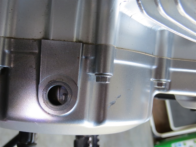
19. Install the generator cover plug (magneto cover cap) with its O-ring. Make sure that the O-ring is in good condition; if it's not, then you'll need to replace it. Put a thin layer of motor oil on the O-ring. The service manual states to tighten the cap to 15 N.m (11 lbf-ft).
20. Install the fuel tank shroud.
21. Install the fuel tank making sure that the rubber cushions / bumpers on the frame are in place. Install and tighten the fuel tank mounting bolts. Reconnect the fuel line (remember to position the clamps) and vacuum hose. Later, make sure that there are no fuel leaks.
22. Reconnect the negative wire to the negative battery terminal. Install the battery retainer plate.
23. Install the seat. Line up the tabs (2) on the seat base with the fuel tank and slide it forward. Install and tighten the two mounting bolts.
24. Install the side covers.
All done!
Previous