2010 Suzuki DR650SE Valve Adjustment - Page 2
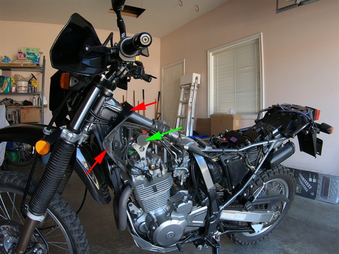
Previous | NextThis page includes the steps for gaining access to check the valve clearances. The following page covers the measurement and adjustment procedure. Measure and adjust the valve clearances when the engine is cold (room temperature, below 35C / 95F).
It is a good idea to clean the motorcycle first, especially the top of the engine and the area above it. You don’t want dirt falling into the engine. It’s also nicer to work on a clean motorcycle.
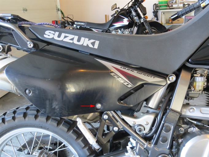
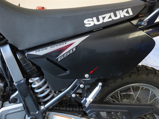
1. Remove the side panels. There is one Philips head bolt and a couple of alignment tabs securing each side panel.
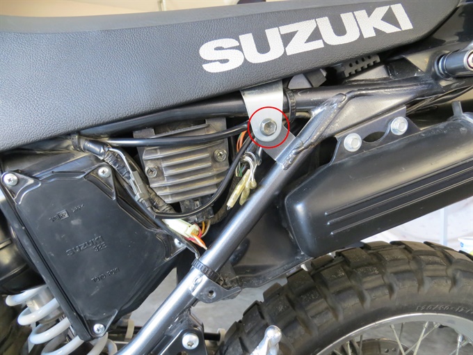
2. Remove the seat. Remove the bolts (one each side) securing the seat. Pull the seat towards the rear of the bike to remove.
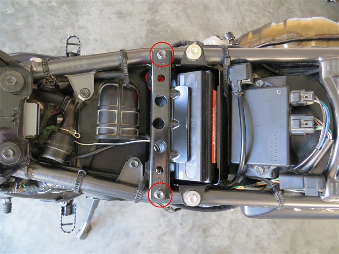
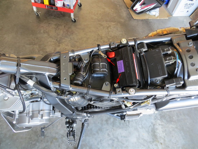
3. Remove the battery securing plate and disconnect the negative wire on the battery.
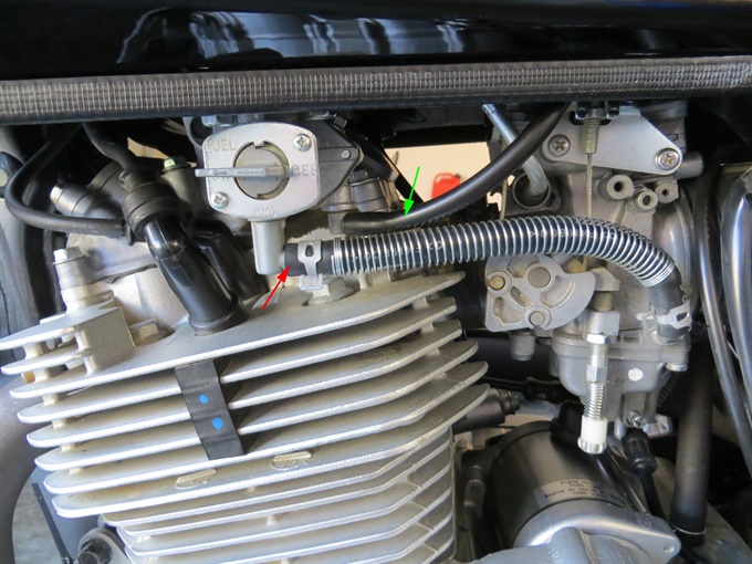
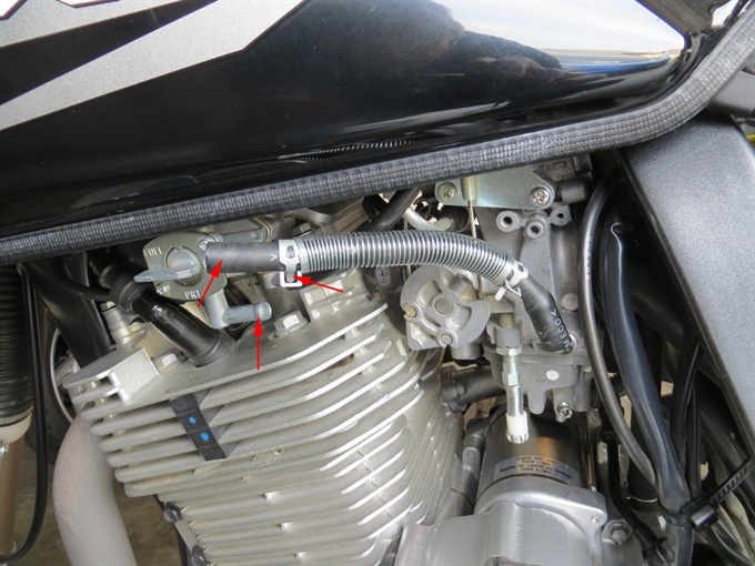
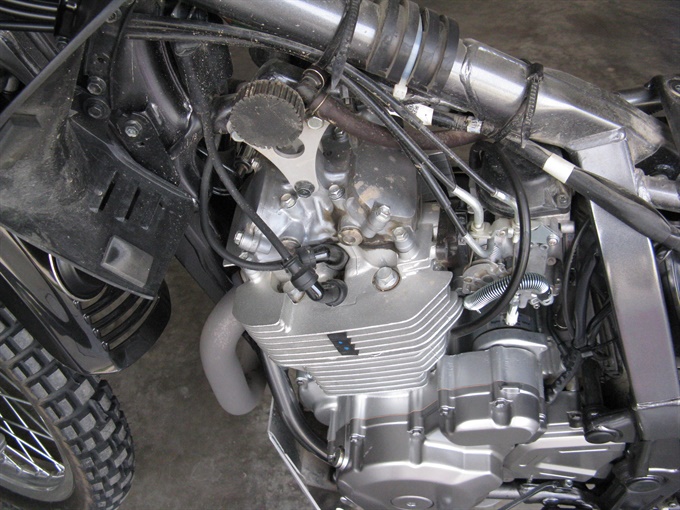
4. Disconnect the fuel line at the petcock. Use pliers to release the fuel line clamp and slide it down the fuel line 3 cm or so. I put pieces of electrical tape to cover the gripping part of the pliers so as not to scratch the clamp tabs / tines. Use a special tool or a flat blade screwdriver to carefully push off the fuel line. Just pulling it off usually doesn't work. Also remove the vacuum hose from the petcock. Inspect the fuel line and vacuum hose. Replace either one if deteriorated. In the second photo below, the fuel line clamp at the carb end has been moved also to enable replacement of the fuel line. Caution: gas is extremely flammable / explosive; vapours may ignite easily, so avoid any sources of combustion / ignition and work in a well-ventilated area.
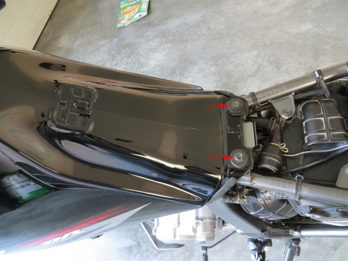
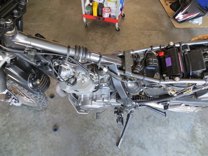
5. Remove the fuel tank. Remove the fuel tank mounting bolts at the rear of the tank. Slide the tank to the rear and lift it off. Place the tank on rags or cardboard on a secure surface.
6. Clean the area above the engine so that dirt does not fall into the engine after the valve inspection caps are later removed. You may also want to wrap the area above the engine with rags to further insure that dirt does not fall into the engine because it is difficult to clean the area completely.
7. Remove the plastic tank shroud for better access to the exhaust valves. There are 2 bolts on each side holding it in place.
8. Disconnect the spark plug caps from the spark plugs. Do not pull on the spark plug wires. For spark plugs that are to be removed, make sure that there is no dirt around the spark plugs that can fall into the engine once the spark plugs are removed. If you have a compressor, blow away any dirt from around the spark plugs. If you don't have a compressor, you can use a vacuum cleaner to suck up any loose dirt. Loosen the spark plug(s) and then inspect for any loose dirt around them. Suck up or blow away any dirt again. Remove the spark plug(s) (see note below) and then use a thin damp cloth on the end of a wooden dowel (craft stick) or a screw driver to carefully clean around the spark plug holes. Inspect the spark plug condition and gap. If the electrodes show signs of erosion, or if the gap is out of spec, remove and the other spark plug if you haven't done so already and inspect it too.
Note that it's not absolutely necessary to remove the spark plug, but if you do not remove it, it will be more difficult to rotate the crankshaft, especially on the compression stroke. Also, as the piston reaches TDC on the compression stroke, there is a tendency for the crank to rotate past TDC because of the pressure in the combustion chamber.
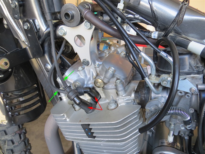
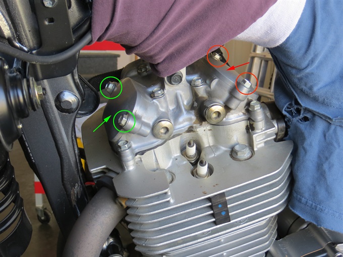
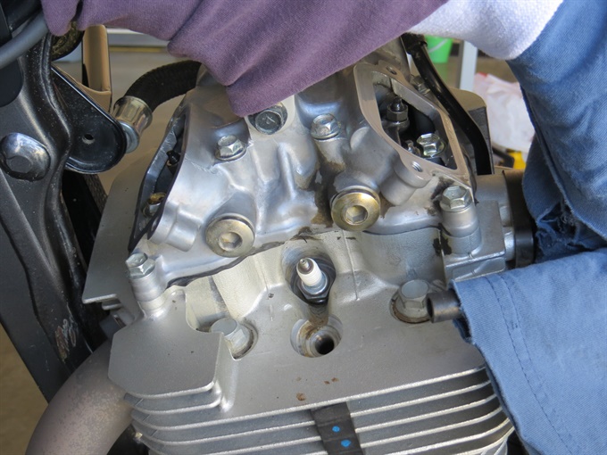
9. Remove the valve inspection caps by removing the two bolts for each. Each valve inspection cap is sealed by a rubber gasket. If removing (or installing) the right-side bolt of the exhaust valve inspection cap from the right-side of the bike, you'll need a 6-inch extension with your ratchet to get at it because of the oil cooler. You may be able to get at the bolt from the left side, but I didn't try.
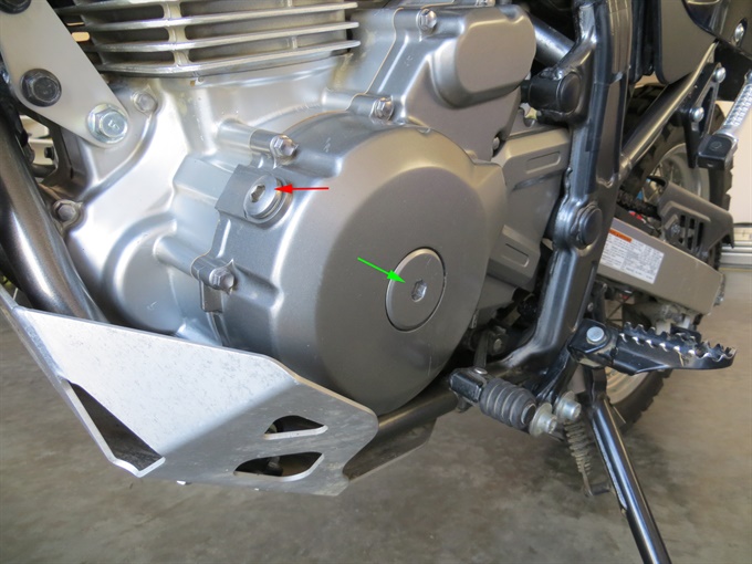
10. Remove the valve timing inspection plug (TDC cap) with a ratchet and 8 mm hex bit.
11. Remove the generator cover plug (magneto cover cap) with a ratchet and a 10 mm hex bit.
Previous | Next