2020 Kawasaki KLX140 Valve Adjustment - Page 2
Previous | NextThis page includes the steps for gaining access to check the valve clearances. The following page covers the measurement and adjustment procedure, as well as putting things back together. Measure and adjust the valve clearances when the engine is cold (room temperature).
With about 9 hours of run time on our KLX140L, the intake valve clearance was about 0.03 mm, and the exhaust valve was about 0.11 mm. Depending on the size of feeler gauges you have, it can sometimes be difficult to make an exact determination. Both valve clearances were adjusted at that time to be in the upper half of their respective ranges. It's better to be loose than to be tight.
With about 90 hours of run time on our 2020 KLX140L, the intake valve clearance was 0.06 to 0.07 mm, and the exhaust valve was approximately 0.15 mm.
It is a good idea to clean the motorcycle first, especially the top of the engine and the area above it. You don’t want dirt falling into the engine. It’s also nicer to work on a clean motorcycle.
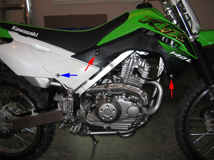
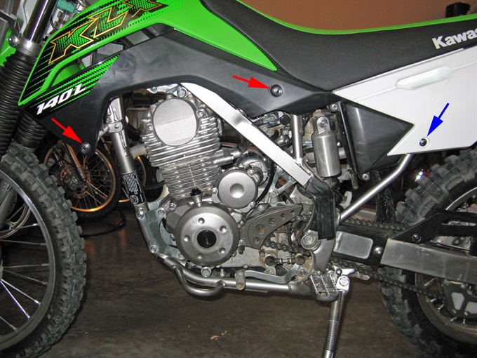
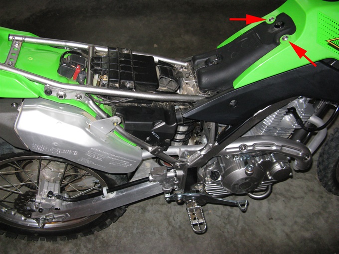
1. Remove the side covers. There is one 8 mm head bolt securing each side cover.
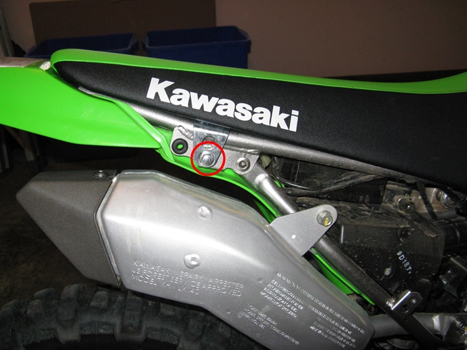
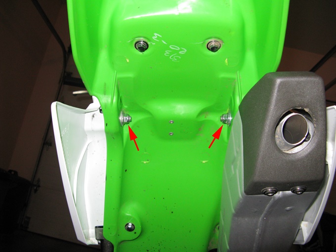
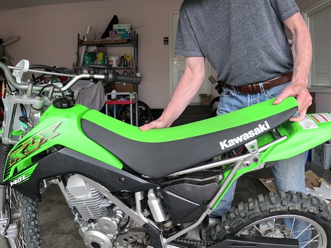
2. Remove the seat. Remove the bolts (one each side) securing the seat. The bolt head is 10 mm and the nut under the fender is 12 mm. I use a 3/8-inch drive ratchet and a 10 mm socket for the bolt and a 12 mm box-end wrench for the nut. Once the bolts are removed, pull up the rear of the seat while pushing down a bit on the seat about a third of the way back from the front (you're bending the seat some) while pulling the seat to the rear of the bike to remove it.
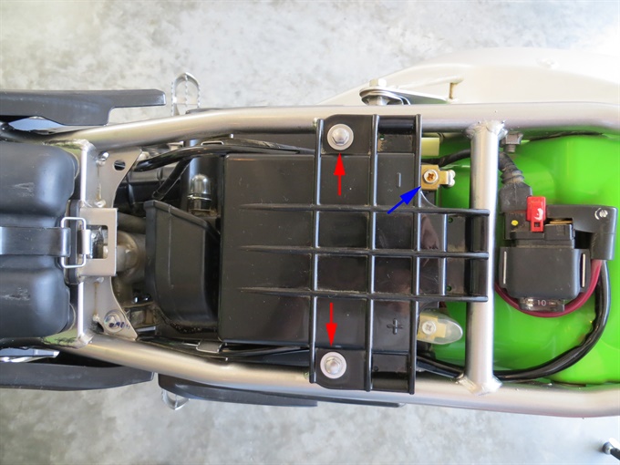
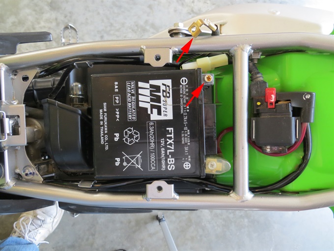
3. Sometimes I disconnect the battery at this point (especially if I might be doing additional work). To do so, remove the plastic battery cover and disconnect the negative wire on the battery.
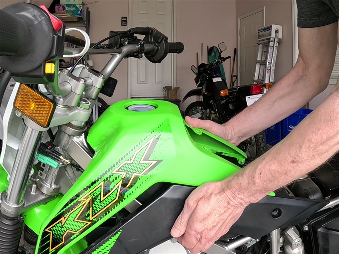
4. Remove the tank shroud (cover). There are two bolts (8 mm head) on each side securing the tank shroud to the frame, and two Philips #3 bolts securing the shroud to the fuel tank. You will need to remove the fuel cap prior to lifting off the tank shroud. Reinstall the fuel cap after removing the tank shroud.
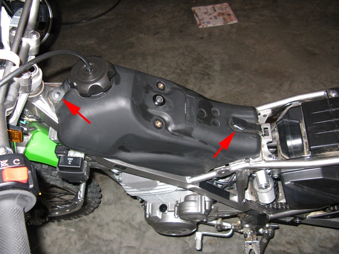
5. Remove the rear retaining strap and front mounting bolt securing the fuel tank. First remove the rubber strap. Next remove the fuel tank mounting bolt (8 mm) at the front of the tank. You may need to loosen the fuel cap slightly in order to access the bolt (tighten the fuel cap afterwards). I use a 1/4-inch drive ratchet and a 6-inch extension with an 8 mm socket.
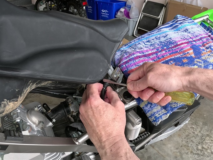
6. Disconnect the fuel line at the petcock. Make sure the petcock (fuel shut-off valve) is in the off/closed position. It may help to prop up the fuel tank a bit for better access. Use pliers to release the fuel line clamp and slide it down the fuel line 3 cm or so. I put pieces of electrical tape to cover the jaws of the pliers so as not to scratch the clamp tabs / tines. Use a special tool or a flat blade screwdriver to carefully push off the fuel line. Just pulling it off usually doesn't work. It may be helpful to spray a bit of silicone spray in the end of the fuel line where it connects to the petcock. A bit of gas may spill out, so you may want to have a rag in place to catch the drips. Inspect the fuel line, and replace it if it looks deteriorated or has become stiff. Caution: gas is extremely flammable / explosive; vapours may ignite easily, so avoid any sources of combustion / ignition and work in a well-ventilated area.
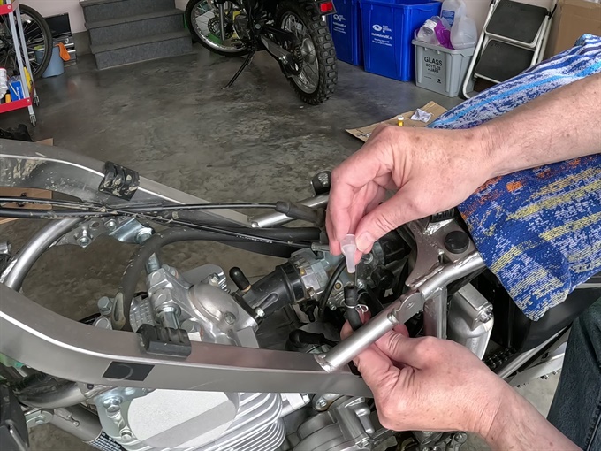
7. Lift off the fuel tank. Place the tank on rags or cardboard on a secure surface. I like to plug the fuel line (I use a plastic cap from a small syringe or pen needle).
8. Clean the area above the engine so that dirt does not fall into the engine after the valve adjustment caps are later removed. You may also want to wrap the area above the engine with rags to further insure that dirt does not fall into the engine because it is can be difficult to clean the area completely.
Although not necessary, you may want to remove the spark plug to make it easier to rotate the crankshaft. Without the spark plug removed, as the piston reaches TDC on the compression stroke, there is a tendency for the crank to rotate past TDC because of the pressure in the combustion chamber. This is not much of an issue on this bike because the engine displacement is small and the engine compression is also low compared to some engines. Now may be a good time to check the condition of the spark plug and the spark plug gap.
To remove the spark plug, disconnect the spark plug cap from the spark plug. Do not pull on the spark plug wire. Make sure that there is no dirt around the spark plug that can fall into the engine once the spark plug is removed. If you have a compressor, blow away any dirt from around the spark plug. If you don't have a compressor, you can use a can of compressed air or you can use a vacuum cleaner to suck up any loose dirt. Loosen the spark plug with an appropriate socket and then inspect for any loose dirt around it. Suck up or blow away any dirt again. Remove the spark plug and then use a thin damp cloth on the end of a wooden dowel (craft stick) or a screw driver to carefully clean around the spark plug hole. Inspect the spark plug condition and gap.
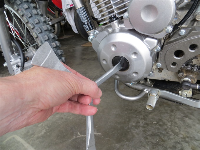
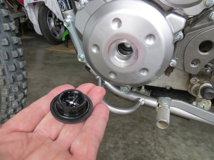
9. Remove the alternator cover center cap. I use a Motion Pro timing plug wrench. The crankshaft bolt (12 mm head) will then be accessible.
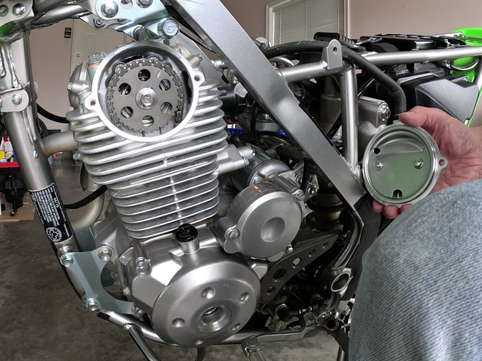
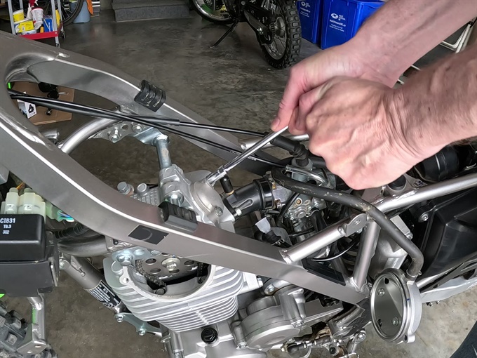
10. Remove the camshaft chain sprocket cover. There is a vent hose attached to the top. You can remove the hose first, or you can leave it attached, in which case you'll need to pass the cover through the frame and over the cylinder head to move it out of the way (which is what I did). Use an 8 mm socket and ratchet to remove the two bolts that hold the cover in place. Pull the cover straight out. The cover is inset into the cylinder head a bit and there is an O-ring around that portion which can make the cover stick a bit.
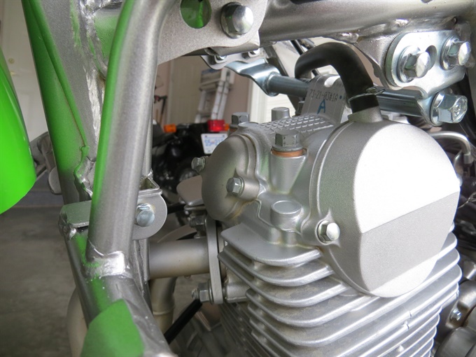
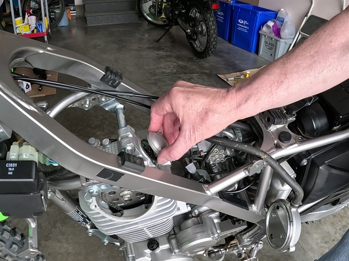
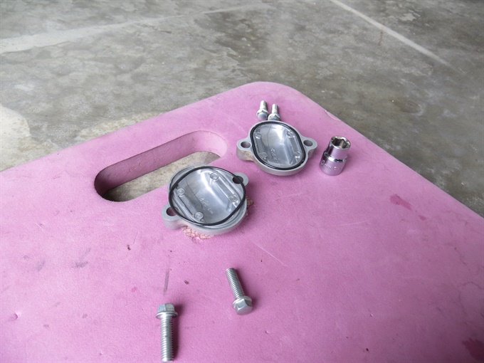
11. Remove the valve adjustment caps. Use a ratchet and a 8 mm socket to remove the two bolts for each. I also use a 6-inch extension. Each valve adjustment cap is sealed by a rubber O-ring (gasket). The caps are the same.
Previous | Next