2020 Kawasaki KLX140 Valve Adjustment - Page 3
PreviousThis page covers the steps for checking and adjusting the valve clearances and putting things back together. Measure and adjust the valve clearances when the engine is cold (room temperature).
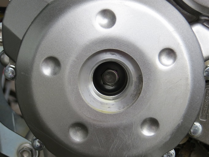
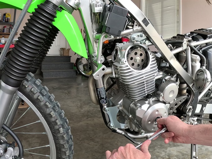
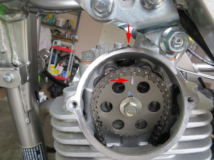
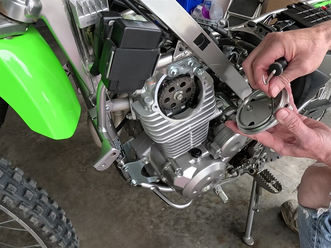
12. Set the engine piston at top dead centre (TDC) on the compression stroke for correct measurement of the valve clearances. Using a 12 mm socket and flex-bar or T-handle on the crankshaft bolt accessible through the alternator cover hole, rotate the crankshaft counter-clockwise until the mark on the camshaft sprocket aligns with the projection on the cylinder head. You should be able to wiggle both intake and exhaust rocker arms at this point.
It’s usually easier if you use a flex-bar or T-handle rather than a ratchet to rotate the crankshaft. Removing the spark plug beforehand makes this easier. If you go past TDC (past the point of aligning the marks), keep rotating the crankshaft counter-clockwise until the marks line up again (at TDC) on the compression stroke. If you cannot wiggle both intake and exhaust rocker arms (valve clearance adjusters) with your fingers, then the piston is not at the top of the compression stroke (or your valves are very tight), so you'll need to rotate the crankshaft counter clockwise a further full revolution and align the marks again. You can also rotate the crankshaft counter-clockwise while observing that the intake valve opens and then closes, and then continuing to rotate the crankshaft until the marks align.
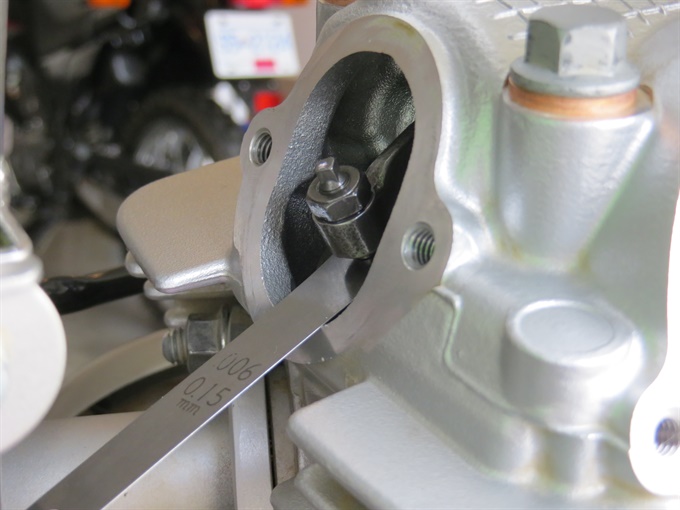
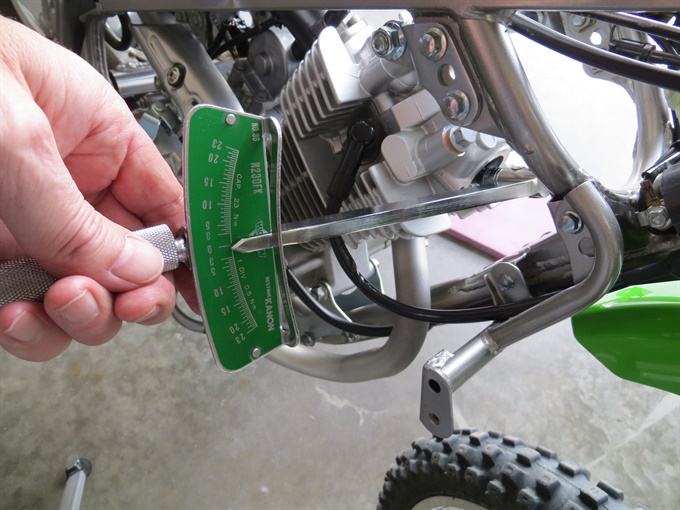
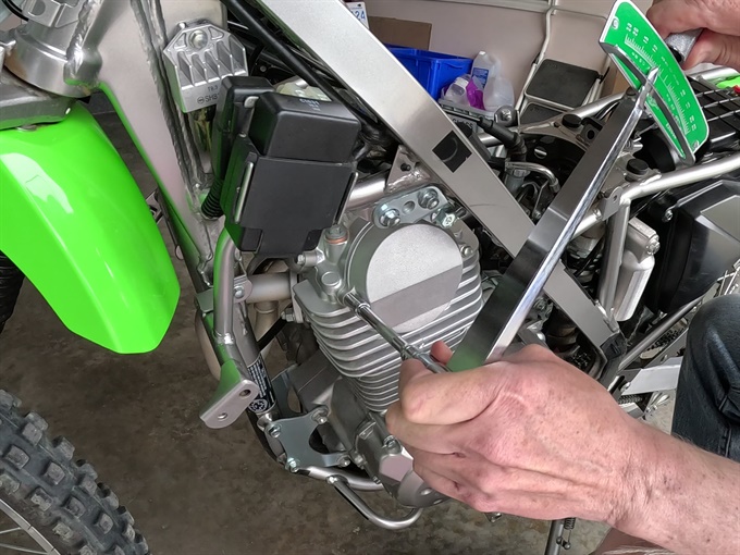
13. Check the valve clearances with feeler gauges and write the measurements down. Insert the feeler gauge in the space between the valve stem and the adjusting screw on the rocker arm. There should be a light drag on the feeler gauge. If the valve clearances are out of spec, you'll need to adjust them, otherwise you can skip ahead and put things back together.
Valve Clearances (per Kawasaki KLX140 service manual) Engine cold: room temperatureIntake: 0.04 - 0.08 mm (0.002 - 0.003 in.)
Exhaust: 0.11 - 0.15 mm (0.0043 - 0.0059 in.)
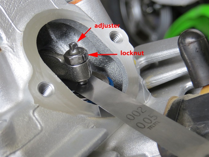
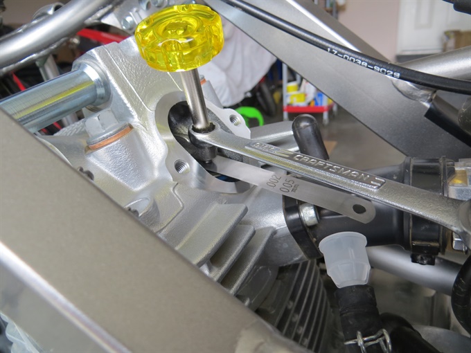
14. Adjust the valve clearances if they are out of specification (or at their limits). Do one valve at a time. Loosen the locknut with a clean 9 mm box-end wrench (or ratchet and a clean 9 mm socket), and then turn the adjuster screw until the valve clearance is in spec. You can turn the adjuster with the correct size feeler gauge (I suggest that you use a feeler gauge of a size equal to, or slightly less than, the upper limit of the allowable range) in place (in the gap) until you feel a bit of resistance, and then very slightly loosen the adjuster and remove the feeler gauge. While holding the adjuster screw (3 mm square end) with the special valve adjuster tool (or a 3 mm wrench), tighten the locknut with the box-end wrench. Check the valve clearance and readjust if necessary.
I try to set the valve clearances close to, or slightly above the mid-point of the range. This often requires me to make multiple attempts. If all you care about is getting the clearances in range, then you can probably complete the task quicker. It's better if the valve clearances are on the looser side than on the tighter side.
Finally, tighten the locknut securely and then recheck the valve clearance. The 2020 KLX140 service manual specifies a torque value of 8.8 N.m (78 in-lb) for the valve adjusting screw locknuts. It has been my experience that the valve clearance gap is reduced during the final tightening of the valve adjuster bolt, so you may want to try to set them initially on the looser end of the range.
15. Recheck both of the valve clearances, and re-adjust them if necessary. Otherwise, record the valve clearances if you haven't already done so.
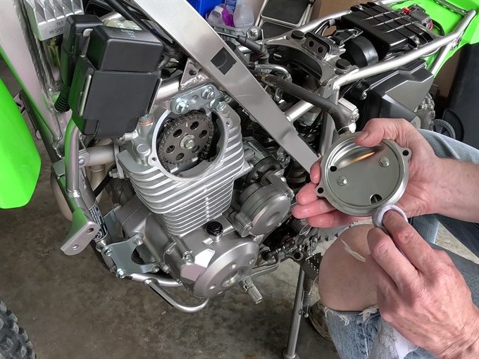
16. Install the valve adjustment caps. Make sure that the mating surfaces are clean and that the rubber O-ring (gasket) is in good condition. The service manual states to apply grease to the O-ring (gasket). Other service manuals have stated to use clean engine oil. The 2020 Kawasaki KLX140 factory service manual specifies a torque of 8.8 N.m (78 in-lb) for the valve adjusting cap bolts. The valve adjuster caps are interchangeable (same part number), and appear to be symmetrical (no obvious specific orientation).
17. If you removed the spark plug, reinstall it and tighten to 13 N.m (115 in.lb). Push the spark plug cap back on.
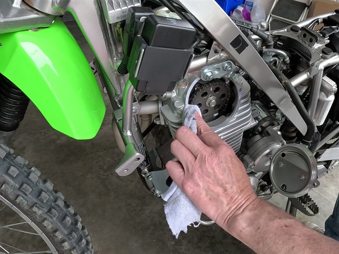
18. Install the camshaft chain (sprocket) cover with its O-ring (gasket). I suggest to carefully remove the O-ring and wipe it off. Also clean the groove that the O-ring resides in. Clean the mating surfaces (cover and cylinder head). The service manual states to apply grease to the O-ring. Tighten the bolts to 8.8 N.m (78 in.lb).
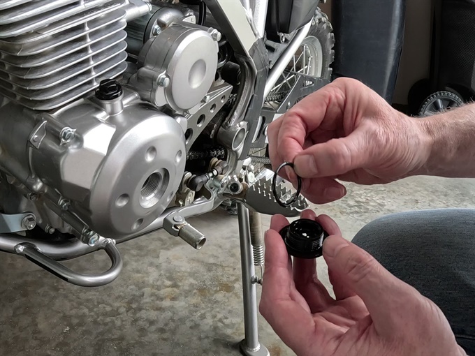
19. Install the alternator cover center cap with its O-ring. Clean (wipe) the O-ring, the cap and the alternator cover hole perimeter. Make sure that the O-ring is in good condition, and if it's not, then you'll need to replace it. The service manual states to apply grease to the O-ring.
21. Install the fuel tank. Position the fuel tank and then connect the fuel line (remember to position the clamp). It may be easier to slip the clamp into its final position on the fuel line before connecting the fuel line to the petcock. Later, make sure that there are no fuel leaks.
Install and tighten the fuel tank mounting bolt (8 mm socket). You may need to loosen the fuel cap a bit to allow room for your 6-inch extension. Next install the rubber strap at the rear of the fuel tank.
20. Install the fuel tank cover/shroud. You'll need to remove the fuel cap first. There are two 8 mm head bolts on each side that attach the shroud to the frame, and two Philips (#3) bolts securing the shroud to the fuel tank. Insert all the bolts, and thread them in a bit by hand, before tightening any of them.
22. Reconnect the negative wire to the negative battery terminal if you disconnected it, and install the plastic battery cover.
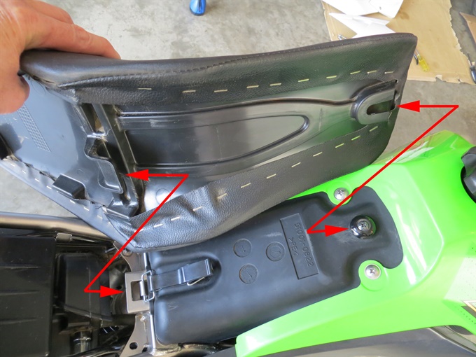
23. Install the seat. Line up the tabs on the seat base with the fuel tank and frame. You need to bend the seat in the middle a bit, and slide it forward and align the metal seat mounting brackets at the rear with the holes in the frame. Start by slipping the front of the seat into place at the fuel tank (lip on underside of seat over the protruding bolt-like part on fuel tank). While holding the rear of the seat up a bit, press down on the seat about 1/3 from front edge (just behind the fuel tank), then lower the rear of seat while also ensuring that the rear metal seat mounting tabs area aligned with the frame (outside frame tubes). Install and tighten the two seat mounting bolts with a ratchet, 10 mm socket and 12 mm box-end wrench.
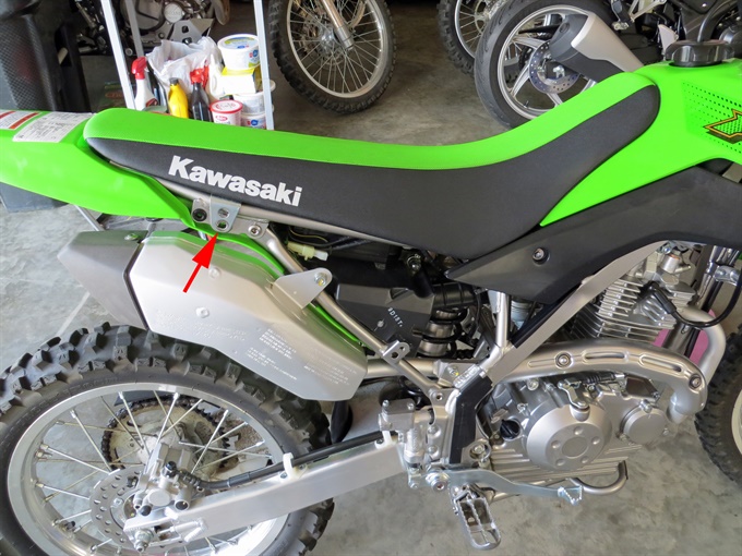
24. Install the side covers. You may want to apply a bit of silicone spray or silicone grease to the rubber grommets first. Each side cover is secured in place by a single 8 mm (head) bolt.
Clean-up and put your tools away.
All done!
Previous